Being Deferential to the Differential
“There’s something wrong with your trusses!”
Few things are less desirable than a customer call-back where a building performance issue can be tied back to your trusses. Cracks in the ceiling drywall. Uneven or sagging floors. Windows and doors not operating properly. These can all be symptoms of a roof or floor truss system where differential deflection is not properly addressed. “Differential deflection can often be difficult to account for as spans and materials change within a system,” says Dan Morris, truss design manager for Apex. “It’s important for designers to have this in the back of their mind as they look at their work and assess their layout.”
What is Deflection?
Deflection is the degree to which a structural member flexes under applied load. The degree of deflection is dependent on two major variables, the stiffness of the member and the load applied to the member. To illustrate, let’s look at a simple beam deflection equation subject to a uniform load:
δ=(5wl^4)/384EI
Where:
w=Load Carried by Beam
l=Span of Beam
EI= Stiffness of Beam
δ =Deflection of Beam
Taking a closer look at this equation, a few things should immediately jump out. First, the two stiffness factors, the ‘E’ known as Modulus of Elasticity, used to determine the beam resistance to deformation, and the ‘I’ known as Moment of Inertia, used to determine the beam resistance to bending, are both located in the lower denominator of the equation. Second, the load and span elements are both located in the upper numerator of the equation. This illustrates that as the beam stiffness increases (or the load and/or span decreases) the deflection is reduced. Conversely, when the load or span increases (or member stiffness decreases) the deflection is increased.


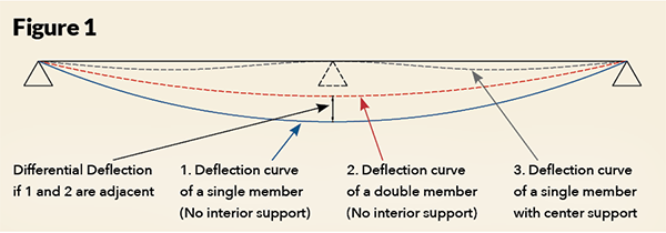
In Figure 1, the deflection curves for three of these four examples are shown to illustrate how stiffening a member, or reducing span by adding additional bearings, can affect the deflection of a member (example 3 is omitted from the figure for clarity, but would be between lines 2 and 3.
It should be noted the addition of an interior bearing like in example 4 not only reduces the maximum deflection but also changes the location of the member’s maximum deflection. “The last thing you want to do when addressing the deflection of one member in a system is create a differential deflection issue with a different member in the system,” says Dan. “Designers need to look at how the whole system comes together in the field.”
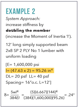
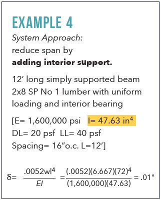
The following calculations provide examples on how the deflection changes with respect to stiffness:
What is Differential Deflection?
Differential deflection is defined as the deflection of one component in a roof or floor system relative to the deflection of an adjacent component. Every system is made out of different components, and each component in this system will have its own deflection. In a roof or floor system, every truss will deflect differently based upon its design characteristics, loading conditions, and location within the framed system.
This only becomes an issue when the differential deflection between any adjacent components in a roof or floor system is high, as it leads to the symptoms mentioned above. Under extreme cases, a high differential deflection can even affect building stability.
Differential deflection is always present, whether due to the system design or how live loads are constantly interacting with individual members within the system. However, there are a some instances where differential deflection can be a significant issue that needs to be carefully tended to, for example:
- when a continuously supported truss is adjacent to an identical truss that is only supported at its ends;
- when a shallower, heavily loaded girder truss in a hip system is adjacent to a deeper, lightly loaded truss;
- when a truss with a flat bottom chord is adjacent to a scissor truss;
- when a heavily loaded partition wall is orientated parallel to the floor truss;
- when a longer span truss is located next to a shorter span truss.
“One common situation where this is an issue is when you have a multi-ply girder in a system with lighter, single-ply trusses running parallel to them. We tell all our designers to pay attention to how the system is laid out around the girders because they will deflect less than the single members adjacent to them.”" says Dan. “For example, if you are running 24" o.c., but there will be a 6" gap between two members within the layout of that system, don’t put that short gap next to the girder. Maximize the space around the girder and put that smaller gap somewhere else in the system.”
What Does Differential Deflection Look Like?
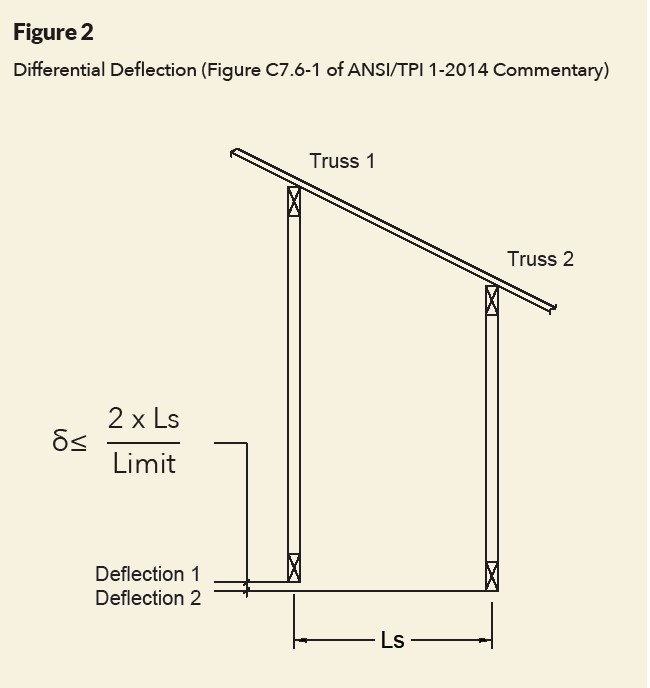
ANSI TPI-1 does not establish requirements for how differential deflection should be addressed. Section 2.3.2.4 of ANSI TPI-1 indicates the building designer (not the truss designer) is responsible for specifying any limitations regarding differential deflection between adjacent trusses. However, Section 7.6.2 within the ANSI TPI-1 commentary states that while limited differential deflection between trusses is not required by ANSI/TPI-1, it includes examples of where it may be objectionable and provides a suggested limit of differential deflection (illustrated in Figure 2):
δ≤(2 x Ls)/Limit
Where:
Ls=spacing between adjacent trusses
Limit=the correct vertical deflection limit given in ANSI/TPI-1 Table 7.6-1.
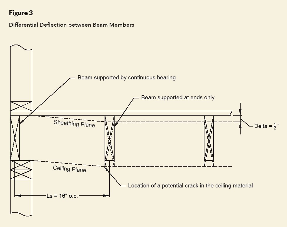
To get a sense for what this means, let’s use the data from example 1 and place two adjacent beams parallel to an end wall (see Figure 3). The calculated differential deflection at the mid-point of the beam not resting on the end wall would be .49” with respect to the top of the wall. If the beam is located 16” away and the ceiling line is intended to be level, it can be determined that differential deflection may be an issue, for when we plug the numbers into the equation we get:
.49>2 x 16=.1778
As a consequence, a shorter or stiffer member is needed to reduce the large differential deflection occurring near the end wall. However, keep in mind the commentary language is not mandatory and is therefore not a requirement by ANSI TPI-1. It is up to the judgement of a qualified engineer on how to address the problem if it is deemed a concern.
“As a rule of thumb, we try to keep or differential deflection to no more than .25”, but it depends largely on the market and the client,” says Dan. “Our production builders specify in their supplier agreements what the acceptable differential deflection is. Here in Florida, we have knock-down ceilings. That treatment hides a lot of imperfections in the ceiling plane, something you don’t have in more northern regions where the ceiling plane is left smooth.”
Bottom Line
If the difference in deflection between two adjacent members in a roof or floor truss system is too large, there may be downstream performance issues that result in customer call-backs. To avoid this headache, designers are encouraged to review their truss system layouts, look for areas where differential deflection may be significant, and determine whether a change in the layout, material or design may be warranted.
This article is the result of a collaboration between the members of the Truss Plate Institute’s Technical Advisory Committee (TPITAC) and SBCA. It is part of a technical article series driven by TPITAC members that seeks to address pertinent engineering topics and provide design best practices.