Crushing It!
It’s imperative for truss designers to consider bearing capacity in their truss designs.
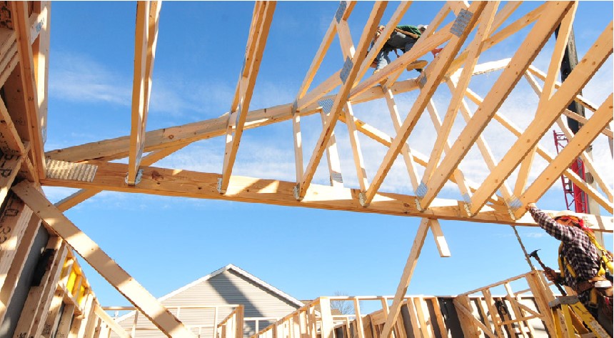
Trusses do amazing things. They span incredibly long distances using triangulated material in a very efficient manner. Yet, while they can create large, airy interior spaces, they do not, in fact, float in the air. Every truss bears onto a wall, beam, another truss, or a load-transferring device like a joist hanger that imposes load onto relatively small surface areas. For truss designers, this is a vital fact to keep in mind. While primarily engaged in the process of laying out a truss to efficiently transfer load to these bearing points, designers must know exactly what the truss is bearing on with respect to size and material.
Size Matters
Construction documents typically include the bearing size, either through specification of a supporting member size, or by reference to a building code. For example, the 2021 International Residential Code (IRC) for One- and Two-Family Dwellings, Section R802.6 states: “The ends of each rafter or ceiling joist shall have not less than 1½ inches (38 mm) of bearing on wood or metal and not less than 3 inches (76 mm) on masonry or concrete. The bearing on masonry or concrete shall be direct, or a sill plate of 2-inch (51 mm) minimum nominal thickness shall be provided under the rafter or ceiling joist. The sill plate shall provide a minimum nominal bearing area of 48 square inches (30.968 square millimeters). In addition, the 2021 International Building Code (IBC), Section 2308.7.3.1 states, “Ceiling joists shall have a bearing surface of not less than 1½ inches (38 mm) on the top plate at each end.” If the construction documents do not specify a bearing area that meets the minimum size requirements of the applicable building code, it’s vital the truss designer communicate with the customer.
It’s also important to note that beyond bearing size, the overall dimensions of the truss, and how it is restrained from lateral movement over bearing locations, matters in the design of the truss. This is beyond the scope of this article, but bearing capacity may have additional limitations that need to be considered.
Material Matters
The next factor a designer has to consider is the material used at the bearing, both for the truss member and the beam or wall top plate. Both members are critical in the calculations for the actual bearing size needed. This is important because it requires consideration of more than just the truss material.
The lumber design property used to check bearing capacity is FCꓕ– the design value in compression perpendicular to grain, often abbreviated as “cperp.” Per the National Design Standard (NDS) 2018 Tables 4A and 4B, example values of for visually graded lumber of a particular species groups include 425 psi (pounds per square inch) for SPF; 625 psi for DFL; 405 psi for HF; and 480, 565 and 660 psi for SP grades of non-dense, unspecified density, and dense types, respectively. Machine stress rated (MSR/MEL) grades may have higher values than these, depending on the grade.
To check the typical reaction capacity of a single-ply truss on a 2x4 wall:
Alternately, to find the bearing width required of a single ply truss with SPF and a maximum gravity reaction of 1975 lbs:
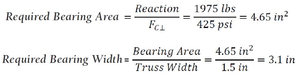
This same calculation produces a required bearing width = 2.1 in for DFL, 3.25 in for HF and 2.33 in for SP of unspecified denseness. These are typical values, but there are further variations in these values that may be required or permitted in high-moisture or high-temperature conditions, for wall plates that extend certain lengths beyond the truss, and with treated lumber.
As this process illustrates, these results differ by a considerable amount. This is important because trusses are often manufactured with different grades and/or species of material than the wall framing. One approach to addressing this is to design the bearing capacity for trusses using the lowest cperp value of any expected wall material. If walls are typically framed in a project’s market using SPF material, that is the material that should be used as the bearing material in the truss design software settings even if the construction documents don’t specify a species group for the bearing support.
Don’t Crush It
It is important to specify the actual bearing sizes for the truss during design. When the minimum required bearing size exceeds the input bearing size, the designer needs to address it because there will likely be excessive crushing of the bottom chord and/or wall top plate, which may elicit complaints from the building owner due to visual deflection, damage to interior finishes near the truss bearing location, or damage to the wood sufficient to cause failure due to loss of strength.
Wood is an organic material that is made up of soft fibers that create its “grain.” The strength of this grain is particularly strong when oriented in a column (think of pushing on a straw longitudinally), meaning the forces are acting parallel with the grain. However, wood is considerably weaker when forces act perpendicular to the grain (again, think of pushing down on a straw laterally, it visibly crushes very easily). When a truss bottom chord and wall top plate meet, the wood grain in both cases is typically perpendicular to the bearing load. If the bearing area is insufficient for the load being transferred, the wood grain may crush excessively in either the wall’s top plate or the truss’ bottom chord, or both.
“This can often be an issue with girder trusses on interior bearing walls, which could carry up to three-fifths of the total truss load,” says Howard Gauger, Engineering Department Manager for Carpenter Contractors of America. “While the end walls may be fine, the load bearing area could be insufficient at the interior bearing.”
Consider Your Options
When boiled down, bearing capacity is about surface area and the ability of the wood to resist crushing. Upgrading lumber species and/or grades in the truss to increase the wood’s resistance to crushing may require communication with the customer as a corresponding upgrade likely needs to be made to the wall top plate or beam material as well. This same condition may exist even without upgrading truss lumber species, if the wall plate is a different material, so again, it is desirable for all truss designs to accurately consider the supporting material species and grade.
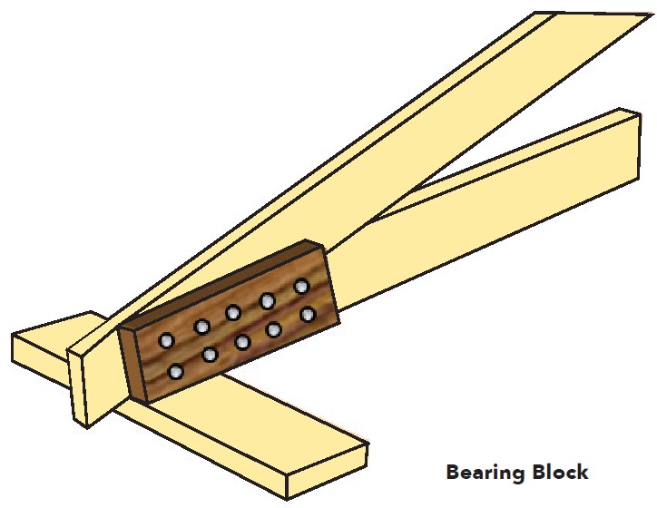
If increasing lumber species and/or grade is infeasible, another option is affixing a bearing block to the side of the truss at the bearing location, which will increase the bearing area without increasing the load applied to the area. “We’ve gone so far as to design a typical bearing block for these situations,” says Howard, “and have standard nailing patters depending on the conditions. We then call it out in the plans.” The bearing blocks are typically specified to be the same grade and species of lumber as the truss, so it’s important to communicate with the customer if using MSR or a higher-grade material that isn’t typically used on the jobsite.
It should also be noted that if a truss has a long scarf cut at the heel, the nailing pattern and quantity of nails needed to affix the block needs to be reviewed to ensure it is possible to achieve. Further, if the location of a tie-in truss on a girder interferes with the attachment of the bearing block, another method will have to be used instead.
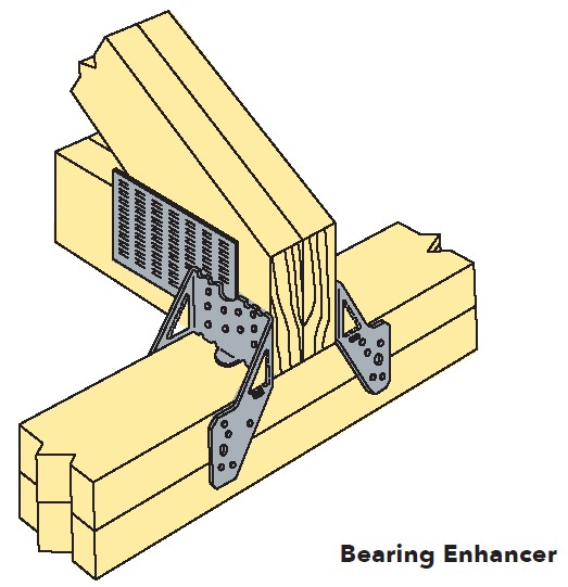
Another option may be to use a metal bearing enhancer, which as the name suggests, is designed specifically to address this issue. If the designer specifies this approach, there must be room on both faces of the truss and on the bearing support to affix the enhancers.
For interior bearings or if a raised heel truss is used, the designer may be able to design the truss so that a web of the truss is run through the chord to the bearing. Doing this changes the bearing stress from compression perpendicular to grain (FCꓕ) to compression parallel to grain (FC), which can be higher than the FCꓕ value. However, this will increase cperp capacity for the truss only and not the top plate of the wall or beam. When using this option, the designer should notify the customer to ensure the bearing member is changed accordingly. In addition, the designer needs to check the web compression capacity because the bottom chord reaction applies to the vertical web as . This is because the bottom chord can crush the vertical web in this condition.
Don’t Leave it to Others
Regardless of the method the designer uses to address an inadequate bearing area, it’s advisable to not leave determination of the bearing size and material to others without clear communication. “It can be tempting to state on the TDD ‘bearing by others,’” says Howard, “but the ‘other’ is just the installer in the field. If you don’t address it in the truss design and through clear communication to the customer, they may not do it right and you end up with a crushing issue that needs to get addressed further down the road.” While the truss designer is typically not the same person who is responsible for the bearing support (wall, beam, or connection), it is appropriate for the truss designer to inform their customer of potential problems so they can communicate the information to the appropriate party designing the bearing support.
This article is the result of collaboration between the members of the Truss Plate Institute’s Technical Advisory Committee (TPITAC) and SBCA. It is part of a continuing series driven by TPITAC members that seeks to address pertinent engineering topics and provide design best practices.