
EFP Truss
Equivalent Fire Performance Truss: A Tested Alternative
The International Residential Code (IRC) mandates fire protection measures for the underside of floor framing members. This is commonly provided by ½-inch gypsum board, 5/8-inch wood structural panel, or other approved material. The code section includes an exception for approved floor assemblies demonstrating equivalent fire performance.
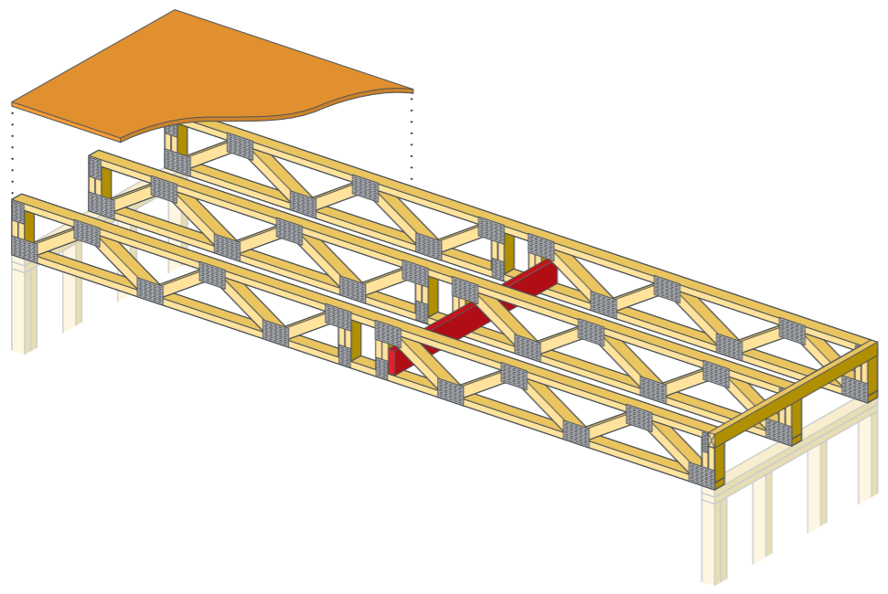
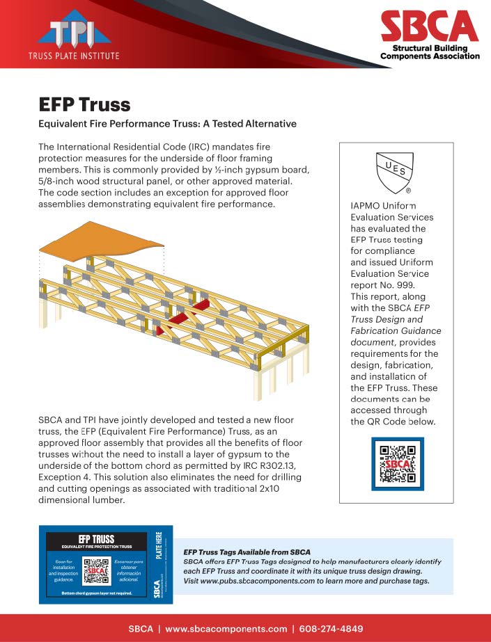
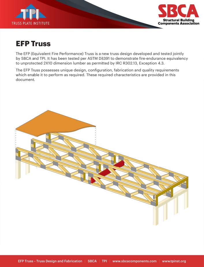
SBCA and TPI have jointly developed and tested a new floor truss, the EFP (Equivalent Fire Performance) Truss, as an approved floor assembly that provides all the benefits or floor trusses without the need to install a layer of gypsum to the underside of the bottom chord as permitted by IRC R302.13, Exception 4.3. This solution also eliminates the need for drilling and cutting openings as associated with traditional 2x10 dimensional lumber.

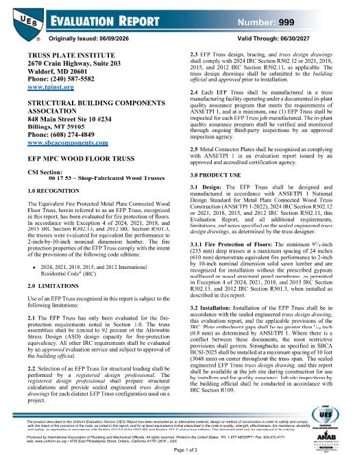
IAPMO Uniform Evaluation Services has evaluated the EFP Truss testing for compliance and issued Uniform Evaluation Service report No. 999. This report, along with the SBCA EFP Truss Design and Fabrication Guidance document, provides requirements for the design, fabrication, and installation of the EFP Truss.
Download the Documents

IRC Requirements
R302.13 Fire protection of floors
Floor assemblies that are not required elsewhere in this code to be fire-resistance rated, shall be provided with a 1/2-inch (12.7 mm) gypsum wallboard membrane, 5/8-inch (16 mm) wood structural panel membrane, or equivalent on the underside of the floor framing member. Penetrations or openings for ducts, vents, electrical outlets, lighting, devices, luminaires, wires, speakers, drainage, piping and similar openings or penetrations shall be permitted.
Exceptions:
1. Floor assemblies located directly over a space protected by an automatic sprinkler system in accordance with Section P2904, NFPA 13D, or other approved equivalent sprinkler system.
2. Floor assemblies located directly over a crawl space not intended for storage or for the installation of fuel-fired or electric-powered heating appliances.
3. Portions of floor assemblies shall be permitted to be unprotected where complying with the following:
3.1. The aggregate area of the unprotected portions does not exceed 80 square feet (7.4 m2) per story.
3.2. Fireblocking in accordance with Section R302.11.1 is installed along the perimeter of the unprotected portion to separate the unprotected portion from the remainder of the floor assembly.
4. Wood floor assemblies using dimension lumber or structural composite lumber equal to or greater than 2-inch by 10-inch (50.8 mm by 254 mm) nominal dimension, or other approved floor assemblies demonstrating equivalent fire performance.
5. Wood floor assemblies less than 600 square feet (55.7 m2) within detached accessory structures with no habitable space above them.
Exception 4
4. Wood floor assemblies using dimension lumber or structural composite lumber equal to or greater than 2-inch by 10-inch (50.8 mm by 254 mm) nominal dimension, or other approved floor assemblies demonstrating equivalent fire performance.
- Minimum baseline is the performance of a 2x10.
- Performance is below that of a gypsum-protected assembly.
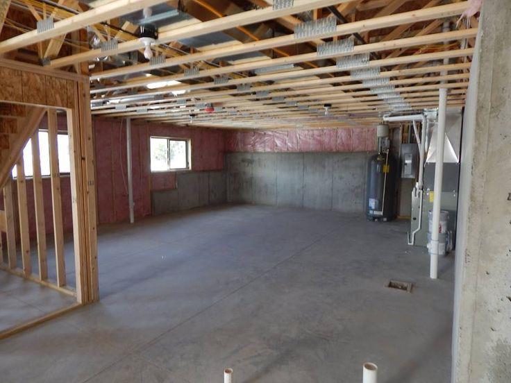
Potential Market
| Houses with Basements | |
|---|---|
| No Basement (Slab on Grade) | 72% |
| Basement | 17% |
| Crawlspace | 11% |
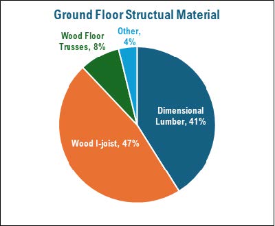
Potential Market
| Market Size | |
|---|---|
| 2023 Single Family Housing Starts | 947,000 |
| Percent with Basements | 16.6% |
| 2023 Houses with Basements | 157,000 |
| New Houses with Finished Basements | 47,000 |
| New Houses with Unfinished Basements | 110,000 |
Fire Testing Objectives
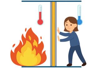
- Ability to resist passage of flames or hot gasses.
- No through-penetrations or flaming on the unexposed face.
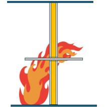
- Ability to provide thermal insulation.
- The temperature rise on the unexposed surface must stay below a certain level.
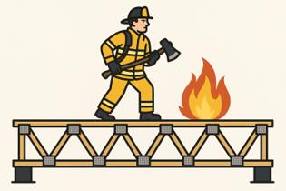
- Ability to maintain structural capacity.
- Must carry a specified load for a specified duration without collapse or a certain level of deflection.
Performance Requirements
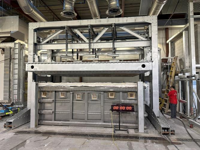
ASTM E119 and D8391
Test Criteria
- Load — 50% of design load.
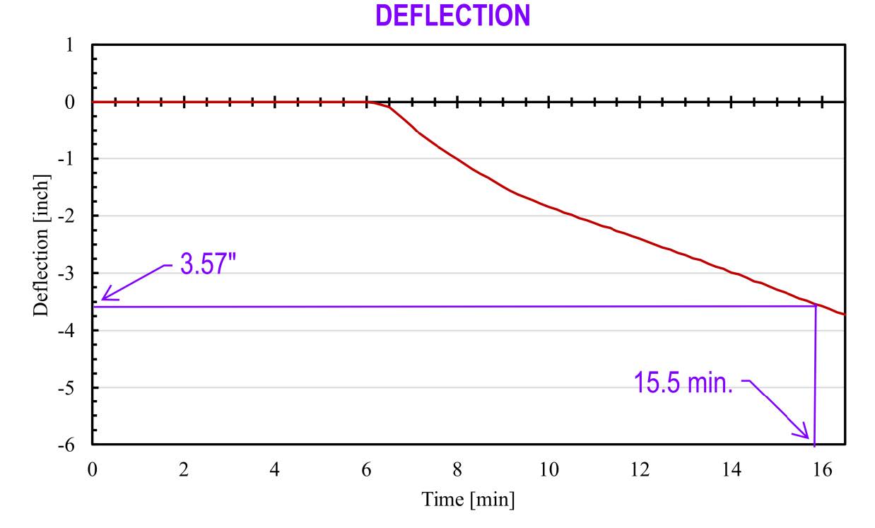
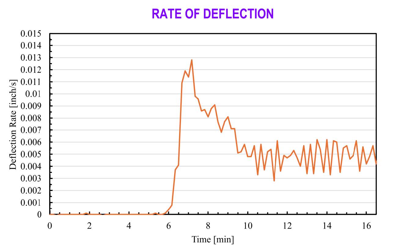
- 15.5 minute duration (based on a calculated 2x10).
- Deflection less than l/40 (3.6 inches for a 12 ft span).
- Change in rate of deflection without reason.
Not a prediction of real fire conditions. Just a comparable benchmark for code compliance.
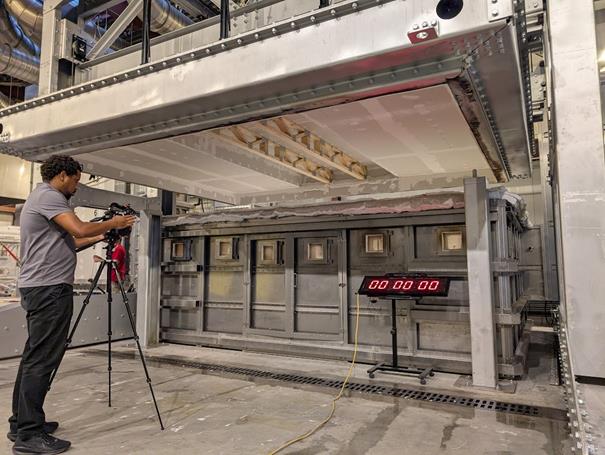
SBCA/TPI Testing
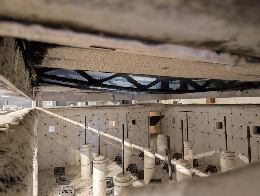
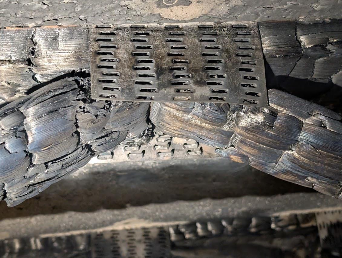
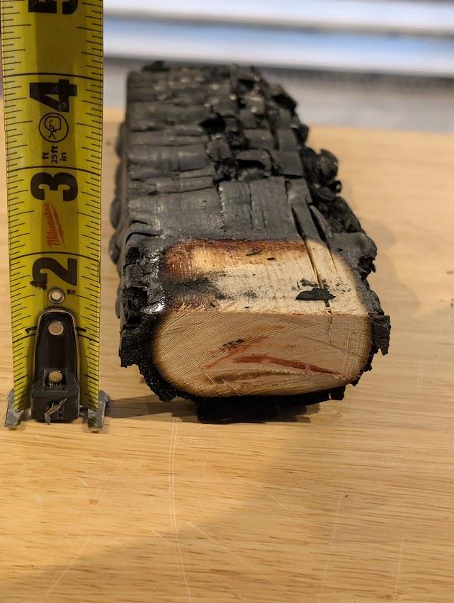
SBCA/TPI Testing
Test Results
Passed load and deflection criteria.
Development of Requirements
- Review of test performance.
- Understanding why it passed.
- Important characteristics:
- Plate tooth length.
- All members #2 grade or better.
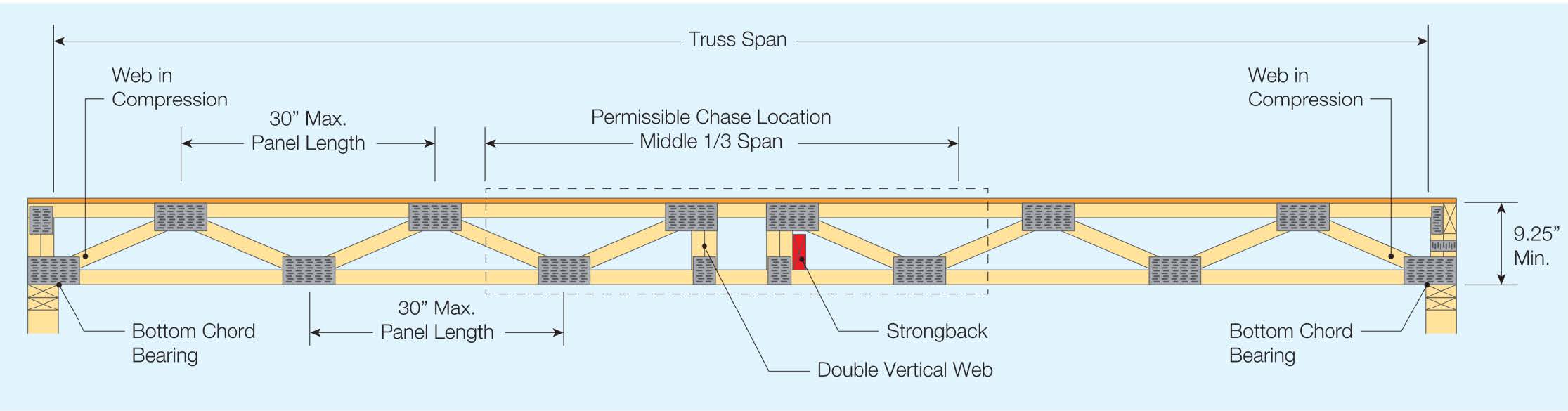
- 30 inch max panels.
- Strongbacks mandatory.
- Double vertical web members.
- Sealed drawing with EFP identification.
- Quality Assurance requirements.
- ERS and additional requirements.
Design Requirements
- Increase total design load 8%.
- Increase added to the live load.
- 45/10/5 loading for a 40/10/5 rated truss.
- Connector plates.
- 3x3 minimum.
- 20 gauge with 0.375″ tooth.
- Fabrication tolerance.
- 20 percent.
- Cq = 0.80.
- Lumber.
- Minimum 2x4, #2.
- Spacing.
- 24″ oc or less.
Truss Design Drawings
- Must be signed by a Registered Design Professional.
- Each EFP Truss shall be uniquely identified by a truss design drawing.
- Include note:
This truss is a special SBCA/TPI EFP Truss designed in accordance with IAPMO Report No. UES ER-999, including overdesigning wood members and metal connector plates by 8 percent, to achieve fire-endurance equivalency to unprotected 2×10 dimension lumber as permitted by IRC R302.13, Exception 4. See also the SBCA/TPI EFP Truss Design and Fabrication document for complete design and manufacturing requirements.
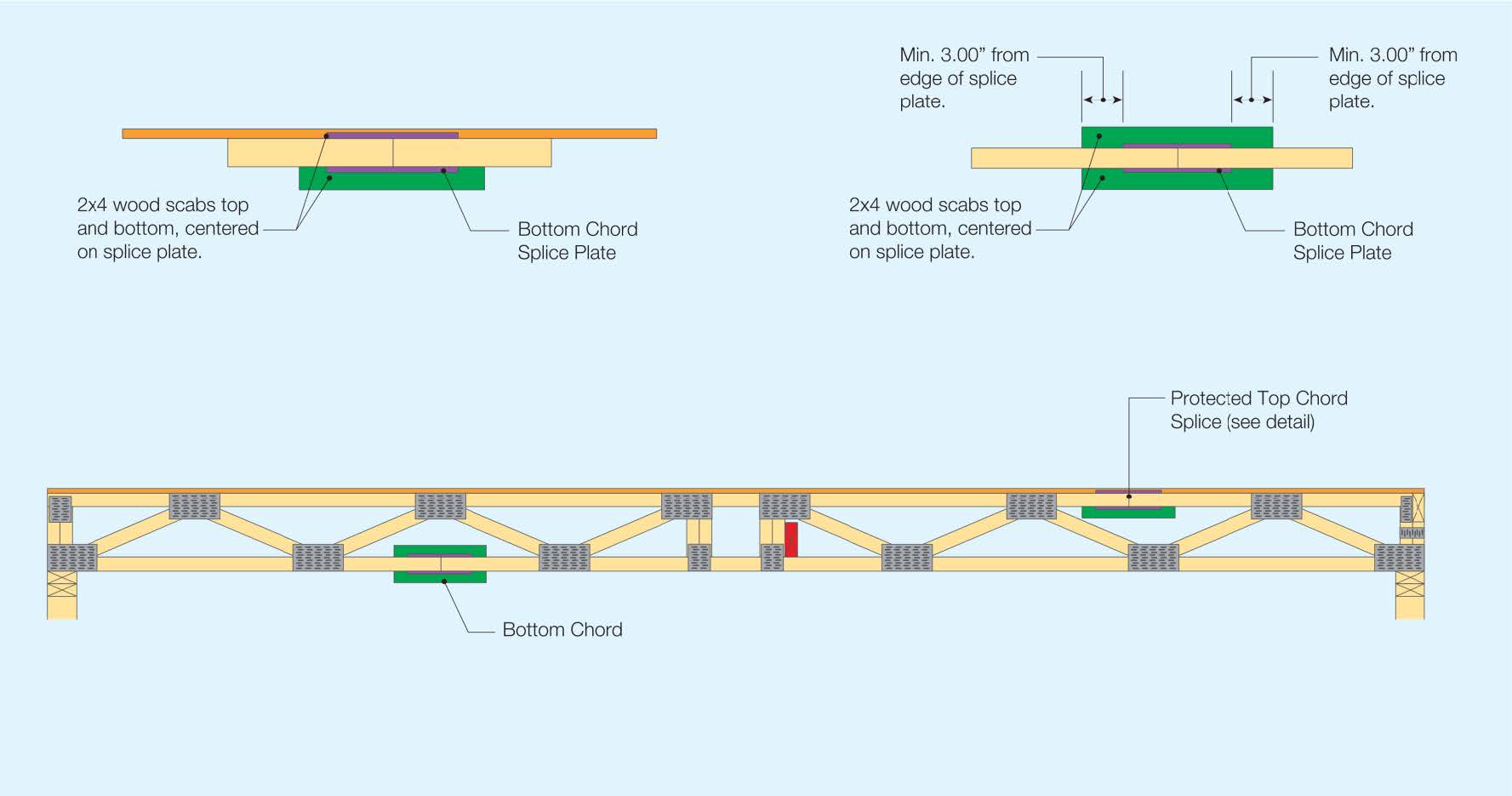
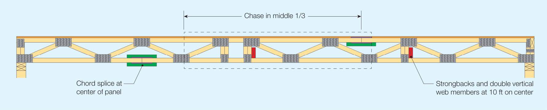
All exposed chord splice plates shall be protected with 2x4 wood scabs centered over the splice plates with a length extending 3-inches beyond each end of each splice plate and fastened with a minimum of (2) 0.120 x 3-inch nails on each side of the splice. Strongbacks shall be installed per standard industry details at 10 ft. oc maximum.
If random representative sampling of trusses as part of the manufacturer's quality program does not include at least one EFP Truss per week per operational set-up location per shift when manufacturing for the week includes an EFP Truss, then an additional inspection shall be performed to include an EFP Truss.
Configuration Requirements
- Warren style with 30-inch maximum panel lengths.
- First web member in compression.
- Bottom chord bearing only.
- Minimum depth = 9.25 inches.
- Chase in the middle 1/3.
- Double vertical webs at 10 ft oc maximum.
- 2x6 strongbacks required.
Configuration Requirements
Chord Splices
Configuration Requirements
Example Layouts
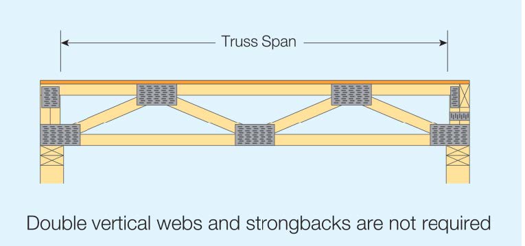
Truss span less than 10 feet
Longer truss spans
Fabrication Requirements
Chord splice

Labeling
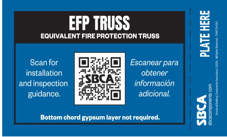
- Each EFP Truss shall be identified with a marking, or affixed label or tag, that coordinates the truss with the truss' unique truss design drawing and identifies the truss as an EFP Truss.
Jobsite package
- IAPMO Report.
- Truss design drawings.
Quality Requirements
- In-plant quality program meeting the requirements of ANSI/TPI 1.
- Third party inspections by an approved inspection agency.
- Metal connector plates shall be recognized as complying with ANSI/TPI 1 in an evaluation report.
- Minimum (1) EFP Truss included in the random sampling when EFP Trusses are being manufactured.
- No plate gaps greater than 1/32″. No toothholding reductions allowed.
Marketing Sheet
EFP Truss Design and Fabrication
Current Activities
Future Documents
- Installation and Inspection
Dedicated Webpage
- Literature
- Evaluation Report
- QR Code on truss tag
Education
- On-line education module
Advocacy
- NAHB
- AWC
- Fire association